4x4 LED Cube
Electronics
About
This 4x4 LED cube was built for my final project in Digital Electronics. I created the cube, the driver circuit, and code to generate the animations. This project does not use a microcontroller, like an Arduino, because I wanted to use components I learned throughout the class. Instead, an EEPROM stores all the data used by the cube.
After the class ended, I redesigned the circuit to be compatable with an Arduino since it would be much easier to build, and similarly, I programmed an Arduino to display the cube animations.
How was it built?
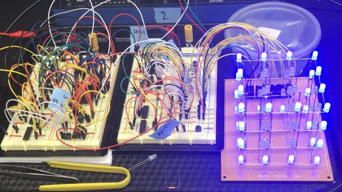
The cube itself consists of 64 LEDs soldered together. Overall, the LED cube works by lighting one row at a time (16 LEDs), and at the same time, selecting which LED in the row should be on or off. By cycling through each row fast enough, above around 3 kHz, the cube appears like all the LEDs are on at the same time through persistence of vision.
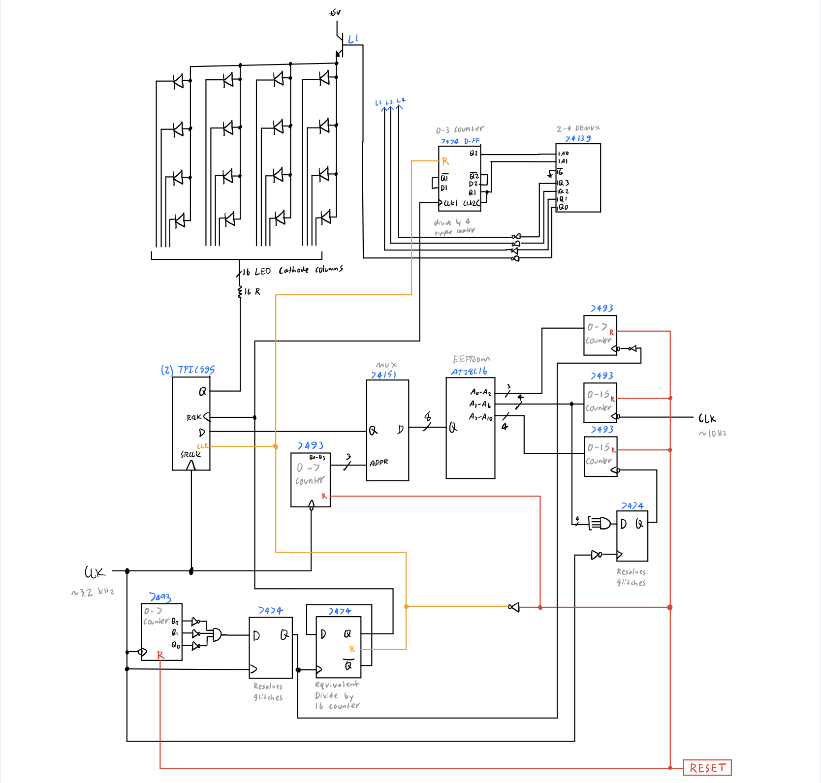
The driver circuit was created using only discrete logic ICs including counters, D-type flip-flops, EEPROM, multiplexers, demultiplexers, and shift registers.
I used Python to create a binary file for the EEPROM. First, I have a text file that contains part of the animations in hexadecimal format. For more complex animations, I wrote Python scripts to generate them. Then, I wrote a basic compiler to convert the text file to a binary file, where it would then be added to the EEPROM through a programmer.
A simulator program was built to aid in the development and debugging process, and this was also written using Python. The simulator reads in a binary file, then displays all the animations sequentially. A video of the simulator is shown below.
Challenges faced
Coming up with the schematic diagram for the driver circuit took a very long time to complete. With such a circuit, each clock pulse is triggering multiple components, and if a single component is off the whole circuit will not work as intended.
While building the circuit, it was challenging to debug at times. Unlike writing software, where if there's an issue the exact line of code is shown, a single misplaced wire in the whole circuit will cause everything to not work. Similarly, since the output of ICs are not instantaneous, it caused glitches (where an output pin goes +5V instead of 0V), and that caused timing issues. In the end, I resolved the glitches by adding a few D-type flop-flops to the circuit.
Gallery
Image of the cube with the full circuit
Full schematic diagram